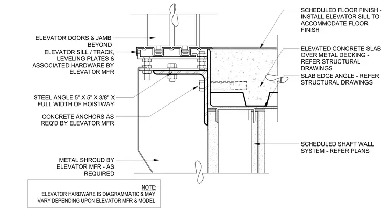
An elevator sill and track assembly mounts to the top leg of a 5 inches by 5 inches by 3/8-inch steel angle spanning the full width of the hoistway. The steel angle is bolted to the edge of an elevated concrete slab over metal decking using concrete anchors specified by the elevator manufacturer. The elevator doors and jamb sit beyond the sill assembly, while a metal shroud encloses the underside as required. A scheduled floor finish meets the elevator sill, and a scheduled shaft wall system aligns below the slab edge.
SCHEDULED FLOOR FINISH - INSTALL ELEVATOR SILL TO ACCOMMODATE FLOOR FINISH SLAB EDGE ANGLE - REFER STRUCTURAL DRAWINGS SCHEDULED SHAFT WALL SYSTEM - REFER PLANS ELEVATOR DOORS & JAMB BEYOND ELEVATOR SILL / TRACK, LEVELING PLATES & ASSOCIATED HARDWARE BY ELEVATOR MFR STEEL ANGLE 5" X 5" X 3/8" X FULL WIDTH OF HOISTWAY CONCRETE ANCHORS AS REQ'D BY ELEVATOR MFR METAL SHROUD BY ELEVATOR MFR - AS REQUIRED NOTE: ELEVATOR HARDWARE IS DIAGRAMMATIC & MAY VARY DEPENDING UPON ELEVATOR MFR & MODEL ELEVATED CONCRETE SLAB OVER METAL DECKING - REFER STRUCTURAL DRAWINGS
Members view this detail in full resolution, download the CAD files (SVG, PDF), and can adapt it in the built-in CAD editor — export DXF, DWG, or PDF.
Start membership