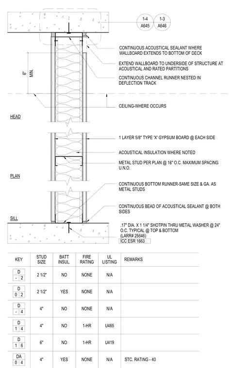
This architectural detail shows the head and sill conditions for a cold-formed metal stud partition framing system. The assembly consists of metal studs spaced at 16 inches on center with continuous top and bottom runners, faced with one layer of 5/8-inch Type X gypsum board on each side. The head detail features a continuous channel runner nested within a deflection track, with wallboard extended to the underside of the structure and sealed with a continuous bead of acoustical sealant. The sill detail is anchored to the substrate using 0.17-inch diameter by 1-1/4-inch shotpins through metal washers at 24 inches on center typical at top and bottom, complemented by continuous beads of acoustical sealant on both sides. Acoustical insulation is included in the cavity where noted.
6" MIN. STUD SIZE KEY BATT INSUL. FIRE RATING UL LISTING REMARKS SILL PLAN HEAD 2 1/2" NO NONE N/A 4" NO NONE 6" NO 1-HR U419 D - 2 D - 4 D 1 6 EXTEND WALLBOARD TO UNDERSIDE OF STRUCTURE AT ACOUSTICAL AND RATED PARTITIONS 1 LAYER 5/8" TYPE 'X' GYPSUM BOARD @ EACH SIDE CEILING-WHERE OCCURS CONTINUOUS BOTTOM RUNNER-SAME SIZE & GA. AS METAL STUDS .17" DIA. X 1 1/4" SHOTPIN THRU METAL WASHER @ 24" O.C. TYPICAL @ TOP & BOTTOM (LARR# 25646) ICC ESR 1663 CONTINUOUS CHANNEL RUNNER NESTED IN DEFLECTION TRACK METAL STUD PER PLAN @ 16" O.C. MAXIMUM SPACING U.N.O. ACOUSTICAL INSULATION WHERE NOTED CONTINUOUS BEAD OF ACOUSTICAL SEALANT @ BOTH SIDES 4" NO 1-HR U465 D 1 4 CONTINUOUS ACOUSTICAL SEALANT WHERE WALLBOARD EXTENDS TO BOTTOM OF DECK N/A 2 1/2" YES NONE N/A 2 D 0 A645 1-4 A646 1-3 4" YES NONE N/A DA 0 4 STC. RATING - 40
Members view this detail in full resolution, download the CAD files (SVG, PDF), and can adapt it in the built-in CAD editor — export DXF, DWG, or PDF.
Start membership