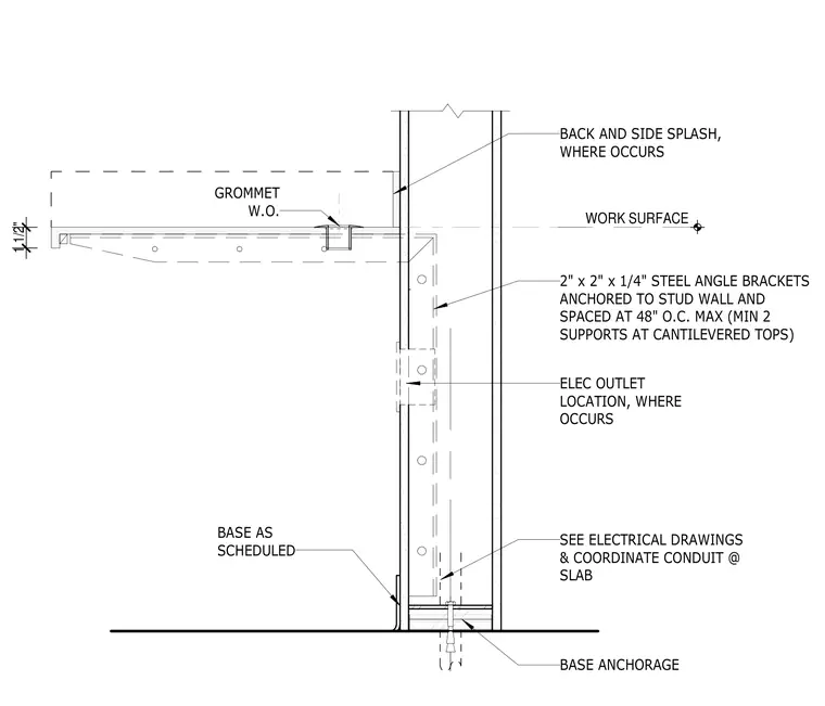
The cantilevered work surface connects to the stud wall using 2" x 2" x 1/4" steel angle brackets spaced at 48" on center maximum, with a minimum of two supports provided at cantilevered tops. A wire organizer grommet penetrates the work surface where required. Back and side splashes abut the stud wall assembly above the work surface. Electrical outlet locations and conduits are coordinated with the slab and electrical drawings. The base assembly sits on the floor slab with a scheduled base finish anchored by a base anchorage device.
BASE AS SCHEDULED SEE ELECTRICAL DRAWINGS & COORDINATE CONDUIT @ SLAB WORK SURFACE ELEC OUTLET LOCATION, WHERE OCCURS 2" x 2" x 1/4" STEEL ANGLE BRACKETS ANCHORED TO STUD WALL AND SPACED AT 48" O.C. MAX (MIN 2 SUPPORTS AT CANTILEVERED TOPS) GROMMET W.O. BACK AND SIDE SPLASH, WHERE OCCURS BASE ANCHORAGE 1 1/2"
Members view this detail in full resolution, download the CAD files (SVG, PDF), and can adapt it in the built-in CAD editor — export DXF, DWG, or PDF.
Start membership