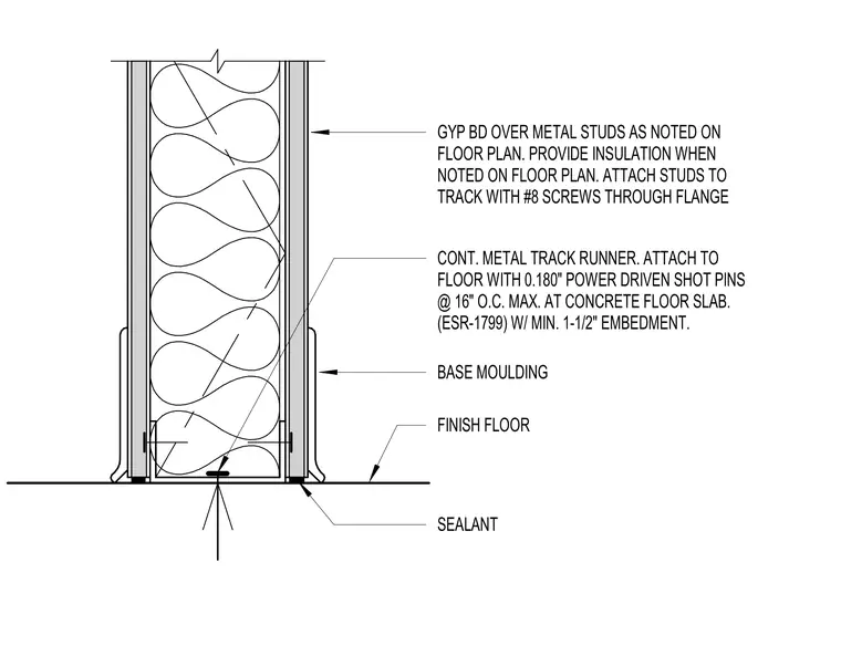
The continuous metal track runner is anchored to the concrete floor slab using 0.180-inch diameter power-driven shot pins spaced at a maximum of 16 inches on center, achieving a minimum embedment of 1-1/2 inches per ESR-1799. Metal studs are attached to the track runner through the flange using number 8 screws. Gypsum board is installed over the studs, with insulation provided as indicated on the floor plans. A sealant bead is applied at the base of the track runner, and base moulding is installed over the gypsum board at the finished floor level.
NOTES: 1. SEE FLOOR PLANS FOR LOCATION OF INSULATION AND FIRE RATINGS (1 HOUR FIRE RATED PARTITION - UL PER DETAIL 14/AD-5) 2. SEE STRUCTURAL DRAWINGS FOR ADDITIONAL FRAMING NOTES. GYP BD OVER METAL STUDS AS NOTED ON FLOOR PLAN. PROVIDE INSULATION WHEN NOTED ON FLOOR PLAN. ATTACH STUDS TO TRACK WITH #8 SCREWS THROUGH FLANGE CONT. METAL TRACK RUNNER. ATTACH TO FLOOR WITH 0.180" POWER DRIVEN SHOT PINS @ 16" O.C. MAX. AT CONCRETE FLOOR SLAB. (ESR-1799) W/ MIN. 1-1/2" EMBEDMENT. BASE MOULDING FINISH FLOOR SEALANT 1
Members view this detail in full resolution, download the CAD files (SVG, PDF), and can adapt it in the built-in CAD editor — export DXF, DWG, or PDF.
Start membership