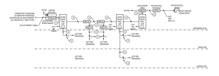
This lighting control system riser diagram details the interconnections between digital network devices, lighting control panels, and building automation systems across lower, main, and mezzanine levels. The schematic shows a digital network segment manager connected to a lighting control enclosure, linking to multiple lighting control panels labeled LCP1, LCP2, and LCP3. Network bridges, relay modules, and low-voltage control drops distribute signals throughout the architecture. An outdoor photocell mounted on the roof facing north connects via conduit and copper wiring to a digital photocell input module and network bridge. Power feeds include 120V emergency power and 277V emergency power runs routed between panels and devices.
Members view this detail in full resolution, download the CAD files (SVG, PDF), and can adapt it in the built-in CAD editor — export DXF, DWG, or PDF.
Start membership