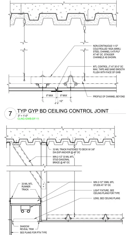
A gypsum board ceiling suspension system is anchored below a concrete-filled metal deck using non-continuous one-and-a-half-inch cold-rolled steel channels spaced at forty-eight inches on center and staggered as shown. A metal control joint is installed at a maximum spacing of thirty feet on center, taped and sanded smooth flush with the face of the gypsum board. The ceiling framing receives minimum two-and-a-half-inch thirty-three mil metal studs at sixteen inches on center alongside light fixtures and shadow reveal trim. Overhead support includes a thirty-three mil track fastened to the deck with three-eighths-inch diameter expansion anchors at forty-eight inches on center, supplemented by minimum two-and-a-half-inch thirty-three mil metal stud diagonal braces spaced at forty-eight inches on center.
8" MAX 8" MAX NON-CONTINUOUS 1-1/2" COLD ROLLED 16GA (64MIL) STEEL CHANNEL 0.475 PLF AT 48" OC. STAGGER CHANNELS AS SHOWN. MTL CONTROL JT AT 30'-0" OC MAX, TAPE AND SAND SMOOTH FLUSH WITH FACE OF GWB PROFILE OF CHANNEL BEYOND 1/2" 33 MIL TRACK FASTENED TO DECK W/ 3/8" DIA EXP ANCHOR @ 48" OC MIN 2-1/2" 33MIL MTL STUDS AT 16" OC LIGHT FIXTURE, SEE CEILING PLANS FOR TYPE LENS, SEE CEILING PLANS SHADOW REVEAL TRIM 33 MIL MTL RUNNER TRACK SEE PLANS FOR PTN TYPE MIN 2-1/2" 33 MIL MTL STUD DIAGONAL BRACE @ 48" OC 3" = 1'-0" 7 TYP GYP BD CEILING CONTROL JOINT CLNG-GWB-DF-11
Members view this detail in full resolution, download the CAD files (SVG, PDF), and can adapt it in the built-in CAD editor — export DXF, DWG, or PDF.
Start membership