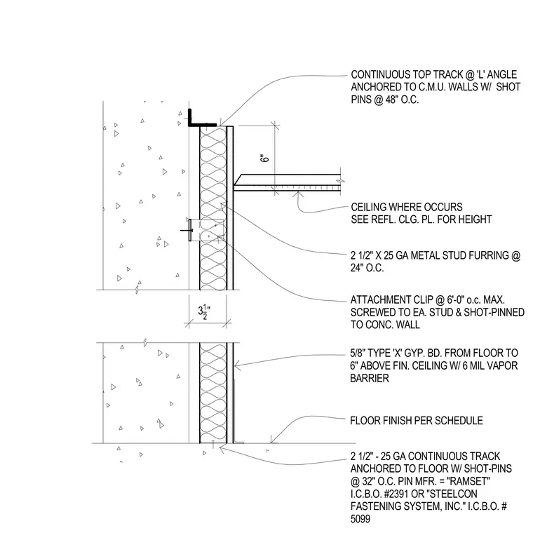
A three-and-a-half-inch cavity space separates a concrete masonry unit wall from a cold-formed steel furring assembly constructed with two-and-a-half-inch by twenty-five gauge metal studs spaced at twenty-four inches on center. Five-eighths-inch Type X gypsum board extends from the floor finish to six inches above the finished ceiling and includes a six-mil vapor barrier. A continuous top track connects to an angle anchored to the masonry wall using shot pins at forty-eight inches on center. A bottom track is anchored to the floor using Ramset or Steelcon shot-pin fasteners spaced at thirty-two inches on center. Attachment clips secured to each stud with screws and shot-pinned to the concrete wall provide intermediate lateral support at six-foot maximum intervals.
3 1_ 2 " 5/8" TYPE 'X' GYP. BD. FROM FLOOR TO 6" ABOVE FIN. CEILING W/ 6 MIL VAPOR BARRIER 2 1/2" X 25 GA METAL STUD FURRING @ 24" O.C. CEILING WHERE OCCURS SEE REFL. CLG. PL. FOR HEIGHT CONTINUOUS TOP TRACK @ 'L' ANGLE ANCHORED TO C.M.U. WALLS W/ SHOT PINS @ 48" O.C. 2 1/2" - 25 GA CONTINUOUS TRACK ANCHORED TO FLOOR W/ SHOT-PINS @ 32" O.C. PIN MFR. = "RAMSET" I.C.B.O. #2391 OR "STEELCON FASTENING SYSTEM, INC." I.C.B.O. # 5099 FLOOR FINISH PER SCHEDULE ATTACHMENT CLIP @ 6'-0" o.c. MAX. SCREWED TO EA. STUD & SHOT-PINNED TO CONC. WALL 6"
Members view this detail in full resolution, download the CAD files (SVG, PDF), and can adapt it in the built-in CAD editor — export DXF, DWG, or PDF.
Start membership