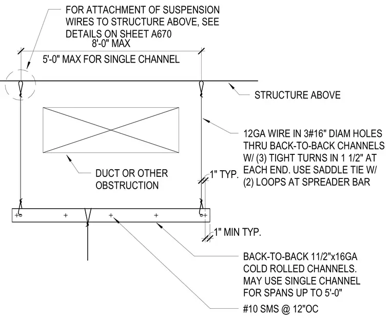
Suspended ceiling carrier assembly consisting of back-to-back one-and-a-half-inch sixteen-gauge cold-rolled channels fastened with number ten sheet metal screws at twelve inches on center. A single channel may be used for spans up to five feet, while back-to-back channels span up to eight feet maximum. Twelve-gauge suspension wires pass through three-sixteenth-inch diameter holes in the channels, secured with three tight turns in one and a half inches at each end. A saddle tie with two loops connects the wire to the spreader bar, routing around building obstructions such as HVAC ducts. Upper suspension wire attachments to the structure above are detailed on sheet A670.
1" TYP. 1" MIN TYP. 5'-0" MAX FOR SINGLE CHANNEL 8'-0" MAX FOR ATTACHMENT OF SUSPENSION WIRES TO STRUCTURE ABOVE, SEE DETAILS ON SHEET A670 STRUCTURE ABOVE DUCT OR OTHER OBSTRUCTION 12GA WIRE IN 3#16" DIAM HOLES THRU BACK-TO-BACK CHANNELS W/ (3) TIGHT TURNS IN 1 1/2" AT EACH END. USE SADDLE TIE W/ (2) LOOPS AT SPREADER BAR BACK-TO-BACK 11/2"x16GA COLD ROLLED CHANNELS. MAY USE SINGLE CHANNEL FOR SPANS UP TO 5'-0" #10 SMS @ 12"OC
Members view this detail in full resolution, download the CAD files (SVG, PDF), and can adapt it in the built-in CAD editor — export DXF, DWG, or PDF.
Start membership