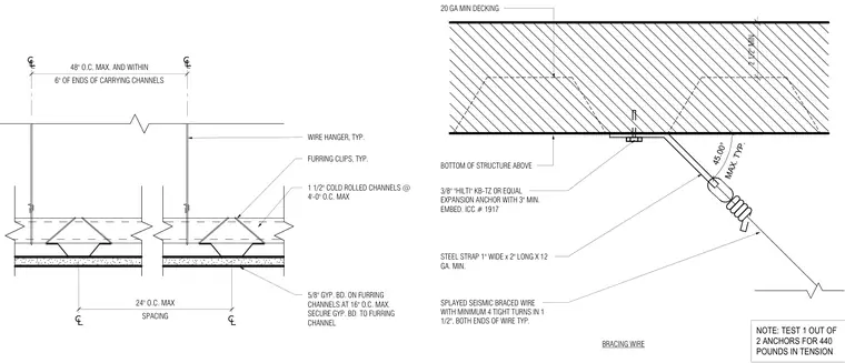
A three-eighths-inch Hilti KB-TZ or equal expansion anchor with a three-inch minimum embedment fastens a one-inch-wide by two-inch-long by twelve-gauge minimum steel strap to the overhead concrete deck for a suspended gypsum board ceiling system seismic splay wire bracing connection. A splayed seismic braced wire connects to the steel strap at a maximum forty-five-degree angle, featuring a minimum of four tight turns in one and a half inches at both ends. The ceiling grid consists of one-and-a-half-inch cold-rolled channels spaced at a maximum of four feet on center, supported by typical wire hangers spaced up to forty-eight inches on center and within six inches of the channel ends. Five-eighths-inch gypsum board is fastened to furring channels spaced at a maximum of sixteen inches on center. A testing note requires one out of every two anchors to be tested for four hundred and forty pounds in tension.
BOTTOM OF STRUCTURE ABOVE MAX. TYP. 45.00° STEEL STRAP 1" WIDE x 2" LONG X 12 GA. MIN. SPLAYED SEISMIC BRACED WIRE WITH MINIMUM 4 TIGHT TURNS IN 1 1/2", BOTH ENDS OF WIRE TYP. BRACING WIRE 20 GA MIN DECKING 2 1/2" MIN 3/8" "HILTI" KB-TZ OR EQUAL EXPANSION ANCHOR WITH 3" MIN. EMBED. ICC # 1917 NOTE: TEST 1 OUT OF 2 ANCHORS FOR 440 POUNDS IN TENSION FURRING CLIPS, TYP. WIRE HANGER, TYP. 1 1/2" COLD ROLLED CHANNELS @ 4'-0" O.C. MAX 5/8" GYP. BD. ON FURRING CHANNELS AT 16" O.C. MAX. SECURE GYP. BD. TO FURRING CHANNEL 6" OF ENDS OF CARRYING CHANNELS 48" O.C. MAX. AND WITHIN SPACING 24" O.C. MAX
Members view this detail in full resolution, download the CAD files (SVG, PDF), and can adapt it in the built-in CAD editor — export DXF, DWG, or PDF.
Start membership