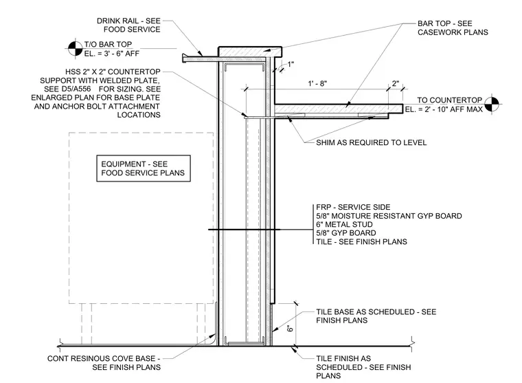
A service bar assembly is framed with six-inch metal studs, finished with five-eighths-inch moisture-resistant gypsum board and fiber-reinforced plastic on the service side, and standard gypsum board with tile on the customer side. Two-by-two-inch hollow structural section supports with welded plates extend from the framing to hold the countertop, leveled using shims as required. A continuous resinous cove base is installed at the floor, while the bar top reaches an elevation of three feet six inches above finished floor, and the customer countertop reaches two feet ten inches maximum above finished floor.
T/O BAR TOP EL. = 3' - 6" AFF TO COUNTERTOP EL. = 2' - 10" AFF MAX FRP - SERVICE SIDE 5/8" MOISTURE RESISTANT GYP BOARD 6" METAL STUD 5/8" GYP BOARD TILE - SEE FINISH PLANS BAR TOP - SEE CASEWORK PLANS TILE BASE AS SCHEDULED - SEE FINISH PLANS TILE FINISH AS SCHEDULED - SEE FINISH PLANS CONT RESINOUS COVE BASE - SEE FINISH PLANS EQUIPMENT - SEE FOOD SERVICE PLANS 1" DRINK RAIL - SEE FOOD SERVICE SHIM AS REQUIRED TO LEVEL 6" 1' - 8" 2" HSS 2" X 2" COUNTERTOP SUPPORT WITH WELDED PLATE, SEE FOR SIZING. SEE ENLARGED PLAN FOR BASE PLATE AND ANCHOR BOLT ATTACHMENT LOCATIONS D5/A556
Members view this detail in full resolution, download the CAD files (SVG, PDF), and can adapt it in the built-in CAD editor — export DXF, DWG, or PDF.
Start membership