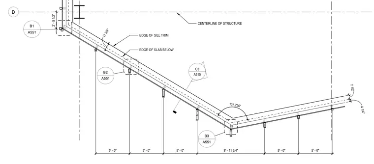
This enlarged corner plan details the geometric layout of an angled architectural facade relative to the structural column grid. The drawing indicates the edge of sill trim and the edge of the slab below with specific dimensional offsets and angular measurements. Grid lines and structural centerlines establish the reference axes for the layout. Detail reference bubbles mark specific connection or framing locations along the perimeter.
D C3 A515 A551 B1 A551 B2 A551 B3 5 ' - 0 " 5 ' - 0 " 5 ' - 0 " 9 ' - 1 1 3 / 4 " 5 ' - 0 " 5 ' - 0 " 1 1 3 / 4 " EDGE OF SILL TRIM EDGE OF SLAB BELOW 1 3 7 . 7 2 6 ° 4 1 / 4 " CENTERLINE OF STRUCTURE 2 ' - 5 1 / 2 " 7 1 / 2 "
Members view this detail in full resolution, download the CAD files (SVG, PDF), and can adapt it in the built-in CAD editor — export DXF, DWG, or PDF.
Start membership