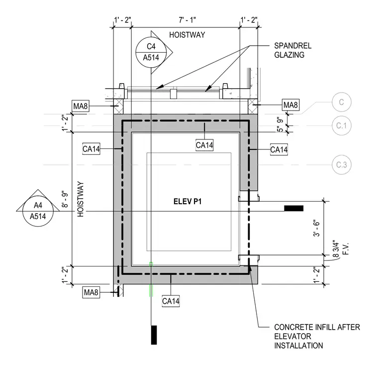
A concrete infill assembly is installed around elevator P1 within a structured hoistway. Spandrel glazing assemblies interface with the hoistway perimeter, accompanied by dimensional layout callouts establishing clearances and wall thicknesses. Grid lines C, C.1, and C.3 align the hoistway boundaries.
C.1 C C.3 ELEV P1 A4 A514 C4 A514 1' - 2" HOISTWAY 8' - 9" 1' - 2" 1' - 2" HOISTWAY 7' - 1" 1' - 2" CA14 CA14 CA14 CA14 MA8 CONCRETE INFILL AFTER ELEVATOR INSTALLATION 1' - 2" F.V. 8 3/4" 3' - 6" 9" 5" SPANDREL GLAZING MA8 MA8
Members view this detail in full resolution, download the CAD files (SVG, PDF), and can adapt it in the built-in CAD editor — export DXF, DWG, or PDF.
Start membership