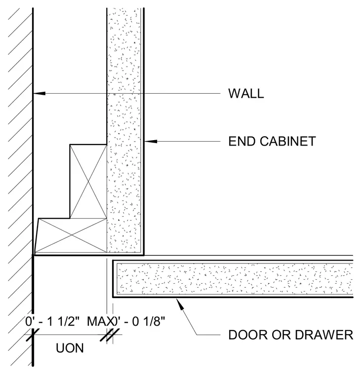
This plan detail shows the intersection of an end cabinet with an adjacent wall, indicating the scribe tolerance and clearance dimensions. A gap of zero feet zero and one-eighth inch is specified unless otherwise noted, with a maximum scribe allowance of zero feet one and one-half inches. The detail provides the necessary spatial relationship between the casework components and the wall finish for millwork installation.
Members view this detail in full resolution, download the CAD files (SVG, PDF), and can adapt it in the built-in CAD editor — export DXF, DWG, or PDF.
Start membership