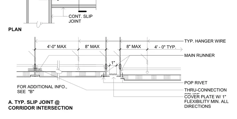
A typical slip joint at a corridor intersection ceiling features a continuous slip joint and a cover plate providing a minimum of one inch of flexibility in all directions. Main runners are supported by typical hanger wires spaced up to four feet on center maximum, with closer eight-inch maximum spacing near the joint. A cover plate is secured using pop rivets at the thru-connection splice. The joint allows for differential movement across the corridor intersection.
4'-0" MAX 8" MAX 4' - 0" TYP. FOR ADDITIONAL INFO., SEE "B" A. TYP. SLIP JOINT @ CORRIDOR INTERSECTION PLAN THRU-CONNECTION SPLICE 8" MAX 1" CONT. SLIP JOINT TYP. HANGER WIRE MAIN RUNNER POP RIVET COVER PLATE W/ 1" FLEXIBILITY MIN. ALL DIRECTIONS
Members view this detail in full resolution, download the CAD files (SVG, PDF), and can adapt it in the built-in CAD editor — export DXF, DWG, or PDF.
Start membership