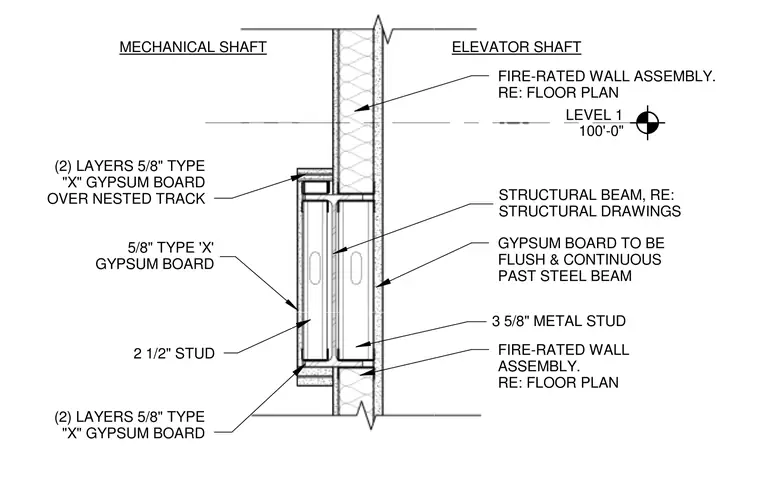
A fire-rated wall assembly separates an elevator shaft and a mechanical shaft at Level 1, established at elevation 100'-0". A structural steel beam acts as the common divider, referenced to the structural drawings. The partition framing incorporates three-and-five-eighths-inch metal studs on the elevator side with a continuous five-eighths-inch Type X gypsum board finish that runs flush past the steel beam. Two-and-one-half-inch studs are framed on the mechanical shaft side, finished with two layers of five-eighths-inch Type X gypsum board over nested tracks at the top and bottom.
LEVEL 1 100'-0" STRUCTURAL BEAM, RE: STRUCTURAL DRAWINGS 5/8" TYPE 'X' GYPSUM BOARD 2 1/2" STUD (2) LAYERS 5/8" TYPE "X" GYPSUM BOARD OVER NESTED TRACK (2) LAYERS 5/8" TYPE "X" GYPSUM BOARD GYPSUM BOARD TO BE FLUSH & CONTINUOUS PAST STEEL BEAM 3 5/8" METAL STUD FIRE-RATED WALL ASSEMBLY. RE: FLOOR PLAN FIRE-RATED WALL ASSEMBLY. RE: FLOOR PLAN MECHANICAL SHAFT ELEVATOR SHAFT
Members view this detail in full resolution, download the CAD files (SVG, PDF), and can adapt it in the built-in CAD editor — export DXF, DWG, or PDF.
Start membership