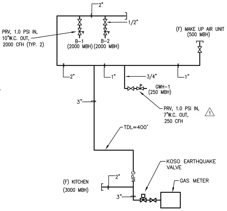
This gas piping schematic details the distribution from the gas meter through a Koso earthquake valve and into main lines sized at three inches. The network feeds two boilers designated B-1 and B-2 at twenty-hundred MBH each, a make-up air unit at five-hundred MBH, a gas water heater designated GWH-1 at two-hundred fifty MBH, and a kitchen connection at thirty-hundred MBH. Each boiler branch includes a pressure-reducing valve rated for one pound per square inch inlet and ten inches water column outlet at twenty-hundred cubic feet per hour. The gas water heater branch incorporates a pressure-reducing valve rated for one pound per square inch inlet and seven inches water column outlet at two-hundred fifty cubic feet per hour. Piping sizes range from one-half inch at equipment drops to three-quarters inch, one inch, two inches, and three inches along main branches.
Members view this detail in full resolution, download the CAD files (SVG, PDF), and can adapt it in the built-in CAD editor — export DXF, DWG, or PDF.
Start membership