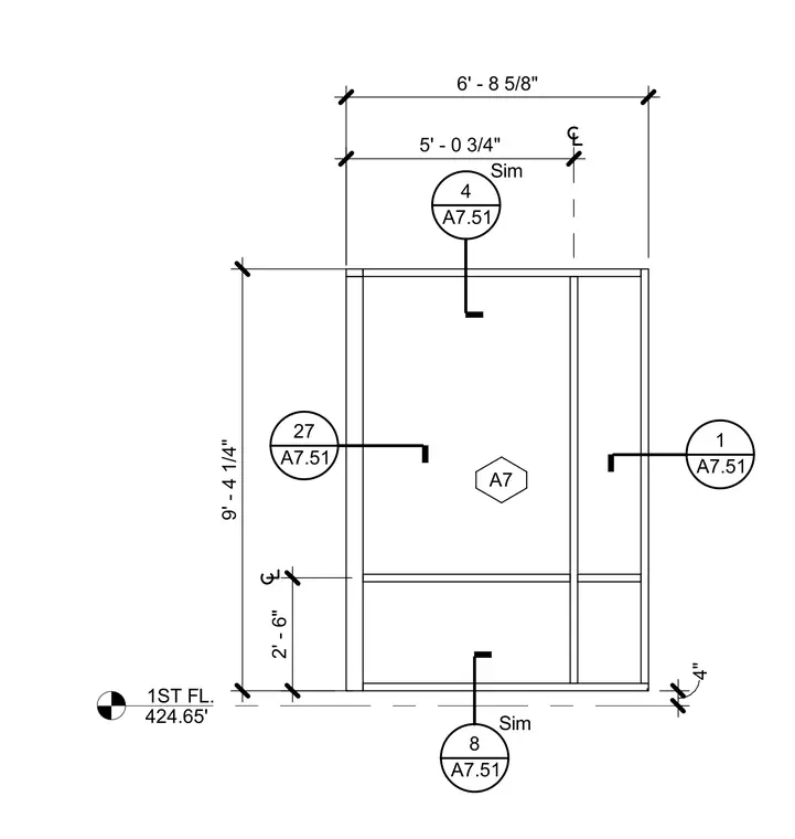
Framed wall layout at the first floor elevation of 424.65 feet with horizontal dimensions of five feet and three-quarters of an inch and six feet and eight-and-five-eighths inches to centerline. Vertical dimensions span nine feet and four-and-a-quarter inches total height with a two-foot-six-inch lower offset and a four-inch base dimension. Detail reference callouts direct to sheet A7.51 for similar or related assembly conditions.
1ST FL. 424.65' A7 4 A7.51 Sim 8 A7.51 Sim 5' - 0 3/4" 6' - 8 5/8" 2' - 6" 9' - 4 1/4" 1 A7.51 4" 27 A7.51
Members view this detail in full resolution, download the CAD files (SVG, PDF), and can adapt it in the built-in CAD editor — export DXF, DWG, or PDF.
Start membership