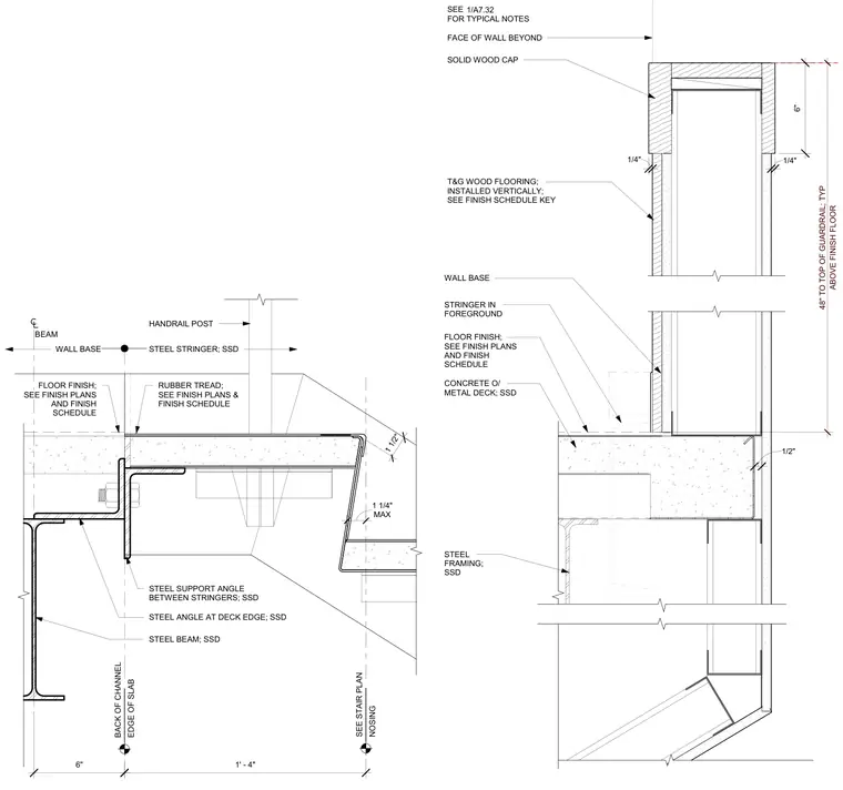
A stair top landing riser and guardrail connection occurs at a concrete-filled metal deck supported by structural steel framing. The concrete slab over metal deck bears on a steel beam with a steel angle at the deck edge. A steel support angle spans between stringers, accommodating a handrail post and a rubber tread at the floor finish. A guardrail with a solid wood cap and vertical tongue-and-groove wood flooring extends to forty-eight inches above the finished floor.
CONCRETE O/ METAL DECK; SSD STEEL FRAMING; SSD SEE FOR TYPICAL NOTES 1/A7.32 FLOOR FINISH; SEE FINISH PLANS AND FINISH SCHEDULE SOLID WOOD CAP FACE OF WALL BEYOND ABOVE FINISH FLOOR 48" TO TOP OF GUARDRAIL; TYP 6" 1/2" STRINGER IN FOREGROUND WALL BASE T&G WOOD FLOORING; INSTALLED VERTICALLY; SEE FINISH SCHEDULE KEY 1/4" 1/4" NOSING SEE STAIR PLAN MAX 1 1/4" EDGE OF SLAB BACK OF CHANNEL BEAM 1 1/2" FLOOR FINISH; SEE FINISH PLANS AND FINISH SCHEDULE STEEL STRINGER; SSD WALL BASE STEEL BEAM; SSD 1' - 4" 6" STEEL SUPPORT ANGLE BETWEEN STRINGERS; SSD STEEL ANGLE AT DECK EDGE; SSD RUBBER TREAD; SEE FINISH PLANS & FINISH SCHEDULE HANDRAIL POST
Members view this detail in full resolution, download the CAD files (SVG, PDF), and can adapt it in the built-in CAD editor — export DXF, DWG, or PDF.
Start membership