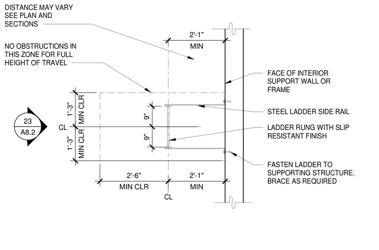
A side-step ladder configuration features steel side rails and rungs with a slip-resistant finish anchored to an interior support wall or structural frame. The assembly maintains a minimum two-foot one-inch clearance from the support face to the ladder centerline, with nine-inch rung spacings and one-foot three-inch minimum side clearances. A designated obstruction-free zone extends for the full height of travel, with travel distances coordinated per plan and sections. Bracing is provided as required to secure the ladder to the supporting structure.
23 A8.2 LADDER RUNG WITH SLIP RESISTANT FINISH STEEL LADDER SIDE RAIL FASTEN LADDER TO SUPPORTING STRUCTURE. BRACE AS REQUIRED FACE OF INTERIOR SUPPORT WALL OR FRAME CL CL NO OBSTRUCTIONS IN THIS ZONE FOR FULL HEIGHT OF TRAVEL DISTANCE MAY VARY SEE PLAN AND SECTIONS MIN CLR 1'-3" MIN CLR 1'-3" 9" 9" MIN CLR 2'-6" MIN 2'-1" MIN 2'-1"
Members view this detail in full resolution, download the CAD files (SVG, PDF), and can adapt it in the built-in CAD editor — export DXF, DWG, or PDF.
Start membership