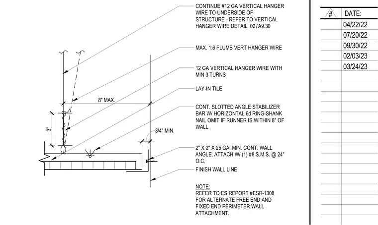
A continuous two-inch by two-inch by twenty-five gauge minimum wall angle is fastened to the finish wall line using number eight sheet metal screws spaced at twenty-four inches on center. A continuous slotted angle stabilizer bar with a horizontal six-penny ring-shank nail is tied to the ceiling grid, with the stabilizer omitted if the runner is within eight inches of the wall. Twelve-gauge vertical hanger wires secure the assembly to the underside of the structure with a maximum one-to-six plumb deviation and a minimum of three turns at the tie-off. Lay-in acoustical tiles meet the perimeter wall angle maintaining a three-quarter-inch minimum clearance.
CONT. SLOTTED ANGLE STABILIZER BAR W/ HORIZONTAL 6d RING-SHANK NAIL OMIT IF RUNNER IS WITHIN 8" OF WALL 2" X 2" X 25 GA. MIN. CONT. WALL ANGLE, ATTACH W/ (1) #8 S.M.S. @ 24" O.C. FINISH WALL LINE LAY-IN TILE CONTINUE #12 GA VERTICAL HANGER WIRE TO UNDERSIDE OF STRUCTURE - REFER TO VERTICAL HANGER WIRE DETAIL 12 GA VERTICAL HANGER WIRE WITH MIN 3 TURNS MAX. 1:6 PLUMB VERT HANGER WIRE NOTE: REFER TO ES REPORT #ESR-1308 FOR ALTERNATE FREE END AND FIXED END PERIMETER WALL ATTACHMENT. 3/4" MIN. 8" MAX. 3" / 02 A9.30 # DATE: 04/22/22 07/20/22 09/30/22 02/03/23 03/24/23
Members view this detail in full resolution, download the CAD files (SVG, PDF), and can adapt it in the built-in CAD editor — export DXF, DWG, or PDF.
Start membership