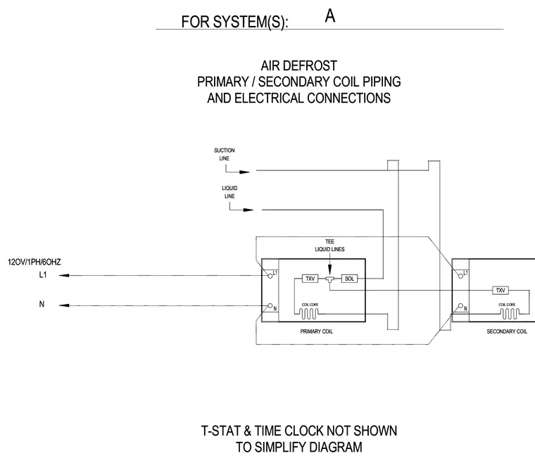
The schematic diagram outlines the piping and electrical connections for an air defrost system with primary and secondary coils. The primary and secondary coils include thermal expansion valves, coil cores, liquid lines, and suction lines connected via a suction tee and solenoid valve. Electrical power is supplied at 120 volts, 1 phase, 60 hertz through line and neutral connections. The thermostat and time clock are omitted from the diagram for simplification.
PRIMARY COIL TXV COIL CORE SUCTION TEE SOL TXV COIL CORE LIQUID LINES LIQUID LINE LINE SECONDARY COIL PRIMARY COIL TXV COIL CORE SUCTION TEE SOL TXV COIL CORE LIQUID LINES LIQUID LINE LINE SECONDARY COIL N L1 N L1 N L1 12OV/1PH/6OHZ A N L1 N L1 N L1 12OV/1PH/6OHZ A TO SIMPLIFY DIAGRAM T-STAT & TIME CLOCK NOT SHOWN AND ELECTRICAL CONNECTIONS FOR SYSTEM(S): PRIMARY / SECONDARY COIL PIPING AIR DEFROST TO SIMPLIFY DIAGRAM T-STAT & TIME CLOCK NOT SHOWN AND ELECTRICAL CONNECTIONS FOR SYSTEM(S): PRIMARY / SECONDARY COIL PIPING AIR DEFROST
Members view this detail in full resolution, download the CAD files (SVG, PDF), and can adapt it in the built-in CAD editor — export DXF, DWG, or PDF.
Start membership