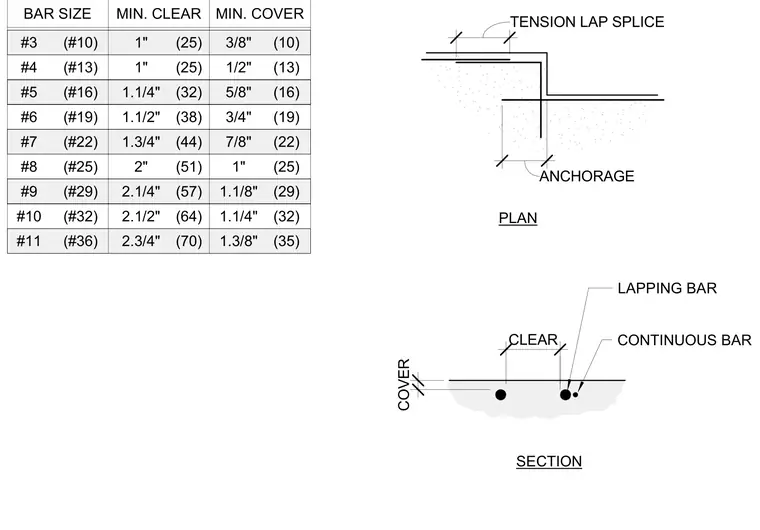
Concrete reinforcement tension lap splice configurations appear alongside a schedule of minimum bar clearance and clear cover dimensions for reinforcing bars ranging from number three to number eleven. The plan view shows the lap splice and anchorage conditions, while the section details the continuous bar, lapping bar, clear spacing, and concrete cover. A complete sizing table correlates US bar sizes with metric equivalents, minimum clear distances, and minimum cover requirements.
3/8" 1/2" 5/8" 3/4" 7/8" 1" 1.1/8" 1.1/4" 1.3/8" 2.3/4" 2.1/2" 2.1/4" 2" 1.3/4" 1.1/2" 1.1/4" 1" 1" #3 #4 #5 #6 #7 #8 #9 #10 #11 BAR SIZE MIN. CLEAR MIN. COVER (#10) (#13) (#16) (#19) (#22) (#25) (#29) (#32) (#36) (70) (64) (57) (51) (44) (38) (32) (25) (25) (10) (13) (16) (19) (22) (25) (29) (32) (35) SECTION PLAN CONTINUOUS BAR LAPPING BAR CLEAR COVER ANCHORAGE TENSION LAP SPLICE
Members view this detail in full resolution, download the CAD files (SVG, PDF), and can adapt it in the built-in CAD editor — export DXF, DWG, or PDF.
Start membership