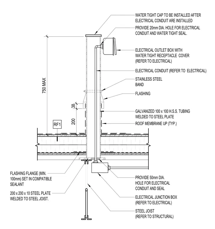
A 100 mm by 100 mm galvanized hollow structural section tubing is welded to a 200 mm by 200 mm by 10 mm steel plate, which in turn is welded to the underlying steel joist. The penetration extends 750 mm maximum above the roof surface and receives a watertight cap installed after the electrical conduit is in place. Roof membrane turns up the tubing with a minimum 100 mm flashing flange set in compatible sealant, secured by a stainless steel band and flashing. An electrical junction box connects below the roof assembly, routing a conduit up through a 50 mm diameter hole into the hollow structural section and out through a 20 mm diameter hole with a watertight seal to an exterior electrical outlet box with a watertight receptacle cover.
200 x 200 x 10 STEEL PLATE WELDED TO STEEL JOIST. 750 MAX GALVANIZED 100 x 100 H.S.S. TUBING WELDED TO STEEL PLATE FLASHING FLANGE (MIN. 100mm) SET IN COMPATIBLE SEALANT ROOF MEMBRANE UP (TYP.) RF1 200 STAINLESS STEEL BAND FLASHING 38 WATER TIGHT CAP TO BE INSTALLED AFTER ELECTRICAL CONDUIT ARE INSTALLED ELECTRICAL OUTLET BOX WITH WATER TIGHT RECEPTACLE COVER (REFER TO ELECTRICAL) ELECTRICAL JUNCTION BOX (REFER TO ELECTRICAL) PROVIDE 20mm DIA. HOLE FOR ELECTRICAL CONDUIT AND WATER TIGHT SEAL. STEEL JOIST (REFER TO STRUCTURAL) ELECTRICAL CONDUIT (REFER TO ELECTRICAL) PROVIDE 50mm DIA. HOLE FOR ELECTRICAL CONDUIT AND SEAL
Members view this detail in full resolution, download the CAD files (SVG, PDF), and can adapt it in the built-in CAD editor — export DXF, DWG, or PDF.
Start membership