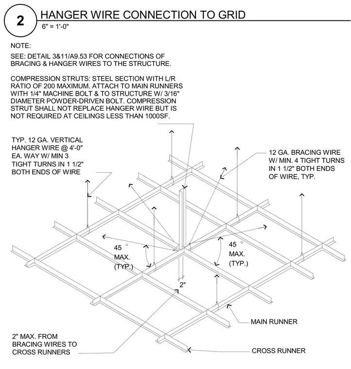
Suspended ceiling grid assembly featuring 12 gauge vertical hanger wires spaced at four feet each way with a minimum of three tight turns in one and a half inches at both ends. Bracing wires of 12 gauge feature a minimum of four tight turns in one and a half inches at both ends and are positioned within two inches of cross runners. Compression struts consist of steel sections with a length-to-radius ratio of 200 maximum, attached to main runners with one-quarter inch machine bolts and to the structure with three-sixteenth inch diameter powder-driven bolts. Compression struts supplement hanger wires and are omitted at ceilings less than 1,000 square feet.
45 MAX. (TYP.) 2" 45 (TYP.) MAX. NOTE: SEE: DETAIL 3&11/A9.53 FOR CONNECTIONS OF BRACING & HANGER WIRES TO THE STRUCTURE. COMPRESSION STRUTS: STEEL SECTION WITH L/R RATIO OF 200 MAXIMUM. ATTACH TO MAIN RUNNERS WITH 1/4" MACHINE BOLT & TO STRUCTURE W/ 3/16" DIAMETER POWDER-DRIVEN BOLT. COMPRESSION STRUT SHALL NOT REPLACE HANGER WIRE BUT IS NOT REQUIRED AT CEILINGS LESS THAN 1000SF. CROSS RUNNERS BRACING WIRES TO 2" MAX. FROM CROSS RUNNER MAIN RUNNER 12 GA. BRACING WIRE W/ MIN. 4 TIGHT TURNS IN 1 1/2" BOTH ENDS OF WIRE, TYP. TYP. 12 GA. VERTICAL HANGER WIRE @ 4'-0" EA. WAY W/ MIN 3 TIGHT TURNS IN 1 1/2" BOTH ENDS OF WIRE 6" = 1'-0" 2 HANGER WIRE CONNECTION TO GRID
Members view this detail in full resolution, download the CAD files (SVG, PDF), and can adapt it in the built-in CAD editor — export DXF, DWG, or PDF.
Start membership