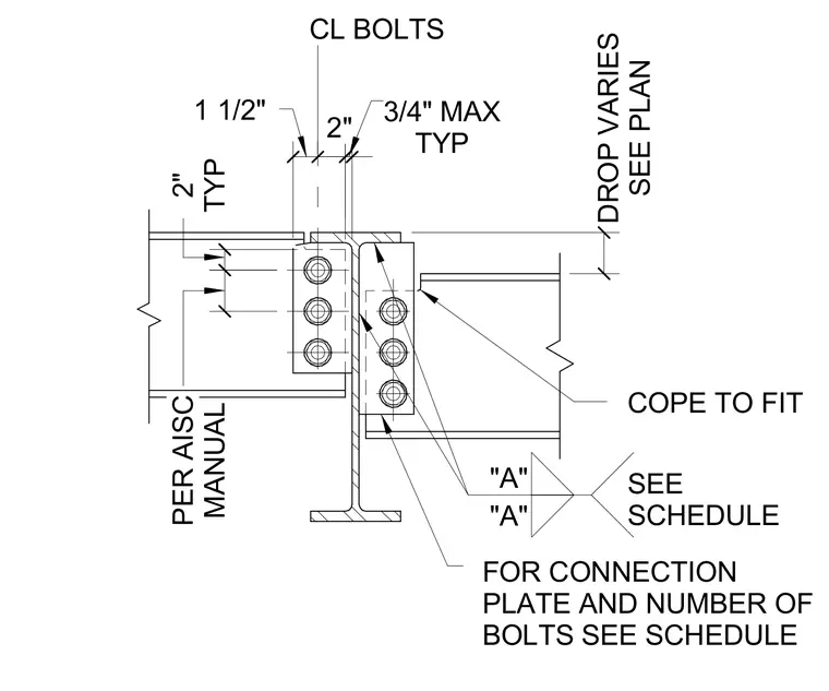
A secondary steel beam frames into a supporting steel girder with a bolted web connection where the top flange is coped to fit. Connection plates and the number of bolts are sized per the structural schedule, maintaining a two-inch typical spacing and a three-quarter-inch maximum clearance. Edge distances and bolt centerlines follow American Institute of Steel Construction manual guidelines, with variable drops sized per plan.
DROP VARIES SEE PLAN 3/4" MAX TYP 2" 1 1/2" 2" TYP PER AISC MANUAL CL BOLTS "A" "A" SEE SCHEDULE FOR CONNECTION PLATE AND NUMBER OF BOLTS SEE SCHEDULE COPE TO FIT
Members view this detail in full resolution, download the CAD files (SVG, PDF), and can adapt it in the built-in CAD editor — export DXF, DWG, or PDF.
Start membership