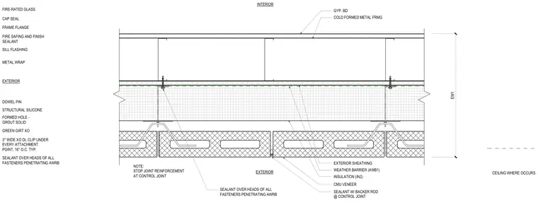
An exterior wall transition and control joint assembly features a CMU veneer backed by insulation, exterior sheathing, and an air-water-resistive barrier. Cold-formed metal framing supports the interior gypsum board ceiling and walls, tied back with three-inch wide XO DL clips placed under every attachment point at sixteen inches on center typical. Sealant with backer rod is applied at the control joint, where joint reinforcement is explicitly stopped. Fasteners penetrating the air-water-resistive barrier receive individual sealant applications over their heads.
INSULATION (IN2) CMU VENEER GYP. BD WEATHER BARRIER (AWB1) SEALANT W/ BACKER ROD @ CONTROL JOINT NOTE: STOP JOINT REINFORCEMENT AT CONTROL JOINT COLD FORMED METAL FRMG EXTERIOR SHEATHING EW1 EXTERIOR INTERIOR SEALANT OVER HEADS OF ALL FASTENERS PENETRATING AWRB CEILING WHERE OCCURS SEALANT OVER HEADS OF ALL FASTENERS PENETRATING AWRB 3'' WIDE XO DL CLIP UNDER EVERY ATTACHMENT POINT, 16'' O.C. TYP. FORMED HOLE - GROUT SOLID METAL WRAP GREEN GIRT XO DOWEL PIN STRUCTURAL SILICONE SILL FLASHING EXTERIOR FIRE-RATED GLASS FRAME FLANGE FIRE SAFING AND FINISH SEALANT CAP SEAL
Members view this detail in full resolution, download the CAD files (SVG, PDF), and can adapt it in the built-in CAD editor — export DXF, DWG, or PDF.
Start membership