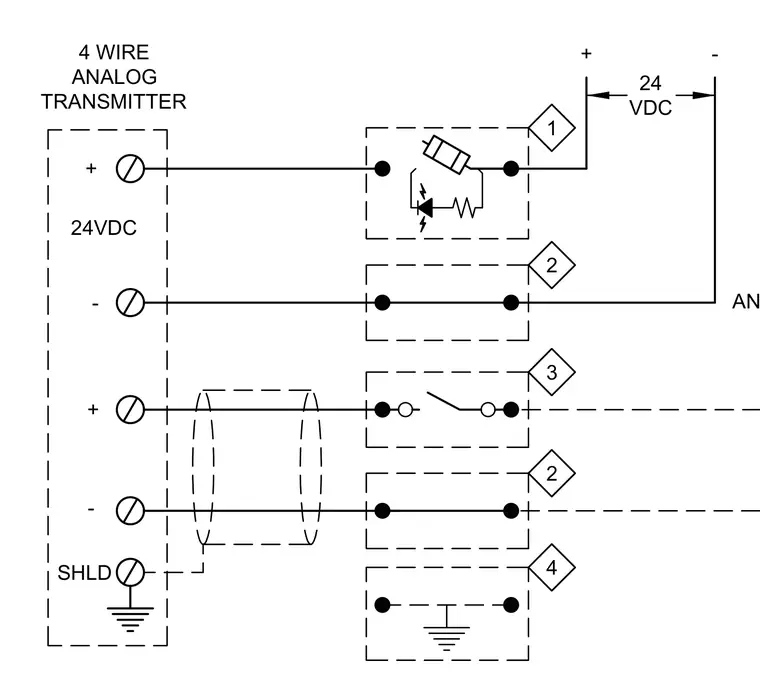
Wiring diagram for a 4-wire analog transmitter showing positive and negative 24VDC power connections along with shielded signal lines routed through terminal blocks. Terminal connections incorporate labeled numbering and grounding symbols for system integration.
4 WIRE ANALOG TRANSMITTER - + 24VDC 4 2 3 2 1 ANALOG INPUT OR 24 VDC - + + - SHLD
Members view this detail in full resolution, download the CAD files (SVG, PDF), and can adapt it in the built-in CAD editor — export DXF, DWG, or PDF.
Start membership