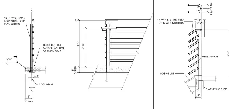
A steel guardrail assembly mounts to an upper floor slab and structural steel floor beam. The guardrail system utilizes one and one-half inch outside diameter by point one-twenty inch wall steel tubing for the top, grab, and mid-rails, supported by one and one-half by one and one-half by three-sixteenth inch structural steel tubing posts spaced at a maximum of five feet on center. The posts anchor into a three-inch minimum block-out filled with concrete poured synchronously with the tread pour. Additional structural framing incorporates an eight by four by one-quarter inch hollow structural section stringer or beam member. A press-in cap finishes the tube ends where specified.
PRESS IN CAP TS8" X 4" X 1/4" 3 1/4" 2" 5" 3" 3" 1 1/2" O.D. X .120" TUBE TOP, GRAB & MID‐RAILS NOSING LINE 3'‐6" 3 1/4" 1/2" BY DESIGN TS 1 1/2" X 1 1/2" X 3/16" POSTS ‐ 5'‐0" MAX. CENTERS 2'‐11" 3'‐6" 3" MIN. CL FLOOR BEAM 6" 3/16" BLOCK OUT. FILL CONCRETE AT TIME OF TREAD POUR CL CL
Members view this detail in full resolution, download the CAD files (SVG, PDF), and can adapt it in the built-in CAD editor — export DXF, DWG, or PDF.
Start membership