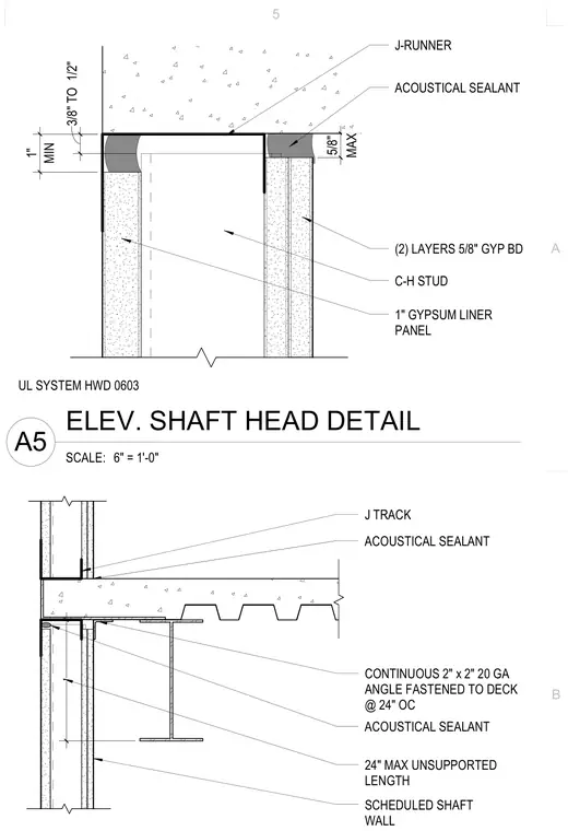
An elevator shaft wall head assembly terminates at an overhead concrete deck and structural steel framing. The shaft wall utilizes scheduled shaft wall framing with C-H studs and a one-inch gypsum liner panel, finished with two layers of five-eighths-inch gypsum board on one side. A J-runner tracks the top of the wall below the concrete deck, sealed continuously with acoustical sealant. A continuous two-inch by two-inch twenty-gauge angle is fastened to the steel deck at twenty-four inches on center, providing a twenty-four-inch maximum unsupported length. This assembly conforms to UL system HWD 0603.
ACOUSTICAL SEALANT CONTINUOUS 2" x 2" 20 GA ANGLE FASTENED TO DECK @ 24" OC . 24" MAX UNSUPPORTED LENGTH J TRACK SCHEDULED SHAFT WALL ACOUSTICAL SEALANT 1" GYPSUM LINER PANEL ACOUSTICAL SEALANT (2) LAYERS 5/8" GYP BD MAX 5/8" MIN 1" 3/8" TO 1/2" C-H STUD J-RUNNER UL SYSTEM HWD 0603 B A 5 SCALE: 6" = 1'-0" A5 ELEV. SHAFT HEAD DETAIL
Members view this detail in full resolution, download the CAD files (SVG, PDF), and can adapt it in the built-in CAD editor — export DXF, DWG, or PDF.
Start membership