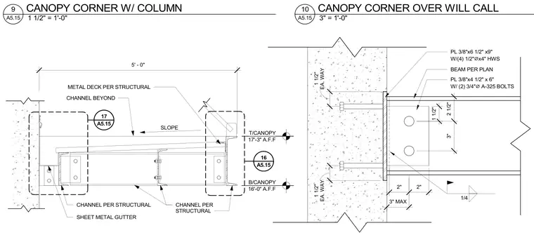
A structural steel canopy corner assembly connects to a concrete or masonry column. The canopy features a sloped metal deck supported by structural channels, terminating in a sheet metal gutter at the edge with a bottom of canopy elevation of 16 feet 0 inches above finished floor and top at 17 feet 3 inches. A connection detail shows a beam attached via a 3/8-inch by 4-1/2-inch by 6-inch plate secured with two 3/4-inch diameter A-325 bolts, paired with an additional 3/8-inch by 6-1/2-inch by 9-inch plate fastened using four 1/2-inch diameter heavy-weight structural studs spaced 1-1/2 inches each way. Fillet welds of 1/4-inch size connect the framing components as specified on the structural drawings.
A5.15 16 A5.15 17 SLOPE METAL DECK PER STRUCTURAL CHANNEL BEYOND CHANNEL PER STRUCTURAL CHANNEL PER STRUCTURAL SHEET METAL GUTTER B/CANOPY 16'-0" A.F.F T/CANOPY 17'-3" A.F.F 5' - 0" PL 3/8"x6 1/2" x9" W/(4) 1/2" ⌀ x4" HWS EA. WAY 1 1/2" EA. WAY 1 1/2" BEAM PER PLAN 1/4 2" 2" 3" MAX PL 3/8"x4 1/2" x 6" W/ (2) 3/4" ⌀ A-325 BOLTS 1 1/2" 2 1/2" 3" 1 1/2" = 1'-0" A5.15 9 CANOPY CORNER W/ COLUMN 3" = 1'-0" A5.15 10 CANOPY CORNER OVER WILL CALL
Members view this detail in full resolution, download the CAD files (SVG, PDF), and can adapt it in the built-in CAD editor — export DXF, DWG, or PDF.
Start membership