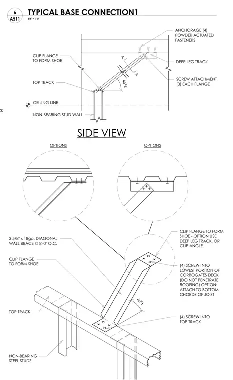
A 3-5/8 inch by 18-gauge diagonal wall brace extends at a forty-five degree angle from the top track of a non-bearing steel stud partition up to the overhead structure. The upper end of the brace is configured with a clip flange forming a shoe secured by four powder-actuated fasteners to a deep leg track or deck, with alternate options for attachment to the lowest portion of corrugated steel deck using four screws without penetrating roofing, or to the bottom chords of open-web joists. Three screws through each flange fasten the clip to the brace member. The lower end connects to the top track of the stud wall with four screws through the shoe flange. The assembly stabilizes non-bearing partitions against lateral loads.
C-CHANNEL TRACK 45°± 45°± SCREW ATTACHMENT (3) EACH FLANGE CLIP FLANGE TO FORM SHOE A TOP TRACK CEILING LINE A SIDE VIEW NON-BEARING STUD WALL ANCHORAGE (4) POWDER ACTUATED FASTENERS CLIP FLANGE TO FORM SHOE - OPTION USE DEEP LEG TRACK, OR CLIP ANGLE (4) SCREW INTO LOWEST PORTION OF CORROGATES DECK (DO NOT PENETRATE ROOFING) OPTION: ATTACH TO BOTTOM CHORDS OF JOIST (4) SCREW INTO TOP TRACK NON-BEARING STEEL STUDS CLIP FLANGE TO FORM SHOE 3 5/8" x 18ga. DIAGONAL WALL BRACE @ 8'-0" O.C. TOP TRACK OPTIONS OPTIONS DEEP LEG TRACK 3/4" = 1'-0" A511 6 TYPICAL BASE CONNECTION1
Members view this detail in full resolution, download the CAD files (SVG, PDF), and can adapt it in the built-in CAD editor — export DXF, DWG, or PDF.
Start membership