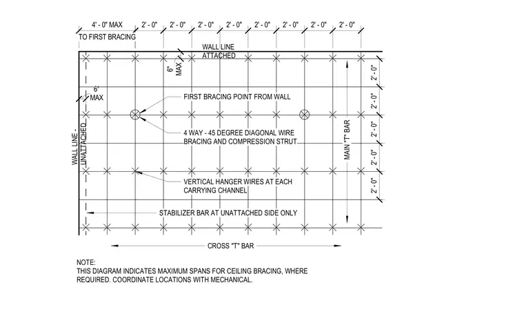
This diagram establishes the maximum spacing requirements for suspended ceiling seismic bracing. It specifies a four-way, forty-five-degree diagonal wire bracing system paired with a compression strut at designated intervals. Vertical hanger wires are required at each carrying channel. A stabilizer bar is installed specifically at the unattached wall line. The layout defines a maximum distance of four feet to the first bracing point from the wall, with additional six-inch maximum offsets for perimeter conditions. Locations must be coordinated with mechanical systems to ensure compliance with seismic bracing requirements.
2' - 0" 2' - 0" 2' - 0" 2' - 0" 2' - 0" 2' - 0" 2' - 0" 2' - 0" TO FIRST BRACING 4' - 0" MAX 2' - 0" 2' - 0" 2' - 0" 2' - 0" 2' - 0" MAX 6" MAX 6" FIRST BRACING POINT FROM WALL 4 WAY - 45 DEGREE DIAGONAL WIRE BRACING AND COMPRESSION STRUT VERTICAL HANGER WIRES AT EACH CARRYING CHANNEL CROSS "T" BAR MAIN "T" BAR STABILIZER BAR AT UNATTACHED SIDE ONLY WALL LINE ATTACHED WALL LINE - UNATTACHED NOTE: THIS DIAGRAM INDICATES MAXIMUM SPANS FOR CEILING BRACING, WHERE REQUIRED. COORDINATE LOCATIONS WITH MECHANICAL.
Members view this detail in full resolution, download the CAD files (SVG, PDF), and can adapt it in the built-in CAD editor — export DXF, DWG, or PDF.
Start membership