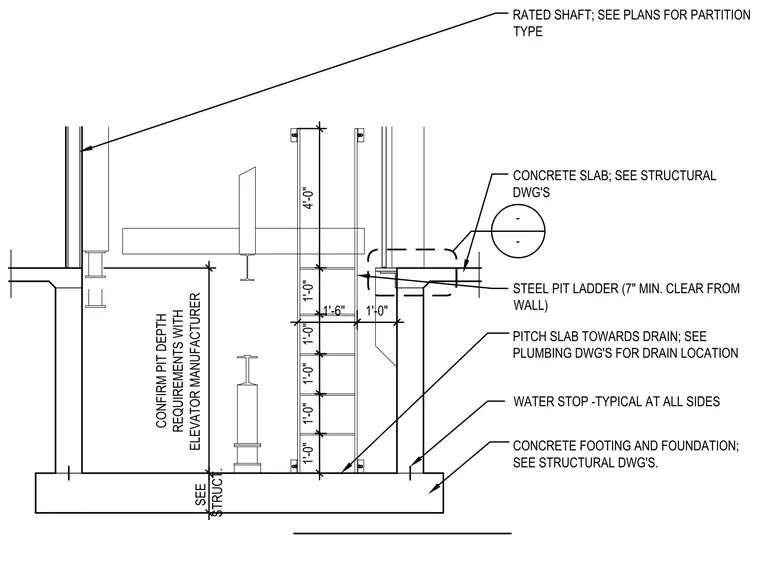
This elevator pit detail shows a concrete footing and foundation supporting concrete walls and slab, with pit depth requirements coordinated with the elevator manufacturer. A water stop is installed typically at all sides of the concrete construction. The concrete slab is pitched towards a drain, with drain location specified on plumbing drawings. Access is provided by a steel pit ladder maintained at a minimum 7 inches clear from the wall. A rated shaft encloses the hoistway above, and structural elements are coordinated with structural drawings.
CONFIRM PIT DEPTH REQUIREMENTS WITH ELEVATOR MANUFACTURER SEE STRUCT. 1'-0" 1'-6" 1'-0" 1'-0" 1'-0" 1'-0" 4'-0" WATER STOP -TYPICAL AT ALL SIDES CONCRETE FOOTING AND FOUNDATION; SEE STRUCTURAL DWG'S. CONCRETE SLAB; SEE STRUCTURAL DWG'S STEEL PIT LADDER (7" MIN. CLEAR FROM WALL) PITCH SLAB TOWARDS DRAIN; SEE PLUMBING DWG'S FOR DRAIN LOCATION RATED SHAFT; SEE PLANS FOR PARTITION TYPE 1'-0" - -
Members view this detail in full resolution, download the CAD files (SVG, PDF), and can adapt it in the built-in CAD editor — export DXF, DWG, or PDF.
Start membership