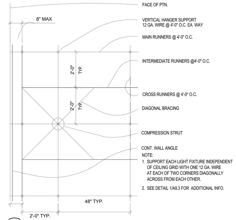
This reflected plan layout details the suspension and seismic bracing requirements for an acoustic ceiling system adjacent to a partition wall. Main runners and intermediate runners span at four feet on center with twelve gauge wire vertical hanger supports spaced at four feet on center each way. Cross runners intersect at four feet on center with diagonal bracing and compression struts tied back to the framing. A continuous wall angle supports the perimeter edge with an eight inch maximum spacing from the partition face. Light fixtures require independent support from the ceiling grid using one twelve gauge wire at each of two diagonally opposite corners.
TYP. TYP. SUPPORT EACH LIGHT FIXTURE INDEPENDENT OF CEILING GRID WITH ONE 12 GA. WIRE AT EACH OF TWO CORNERS DIAGONALLY ACROSS FROM EACH OTHER. SEE DETAIL 1/A9.3 FOR ADDITIONAL INFO. 2. CONT. WALL ANGLE 1. NOTE: CROSS RUNNERS @ 4'-0" O.C. DIAGONAL BRACING COMPRESSION STRUT VERTICAL HANGER SUPPORT 12 GA. WIRE @ 4'-0" O.C. EA. WAY MAIN RUNNERS @ 4'-0" O.C. INTERMEDIATE RUNNERS @4'-0" O.C. FACE OF PTN. 2'-0" 2'-0" TYP. 48" TYP. 2'-0" 8" MAX
Members view this detail in full resolution, download the CAD files (SVG, PDF), and can adapt it in the built-in CAD editor — export DXF, DWG, or PDF.
Start membership