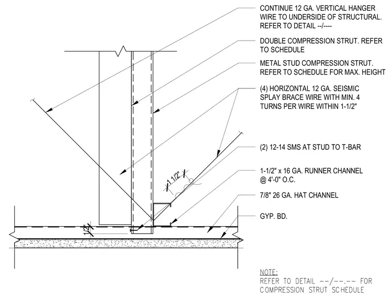
A suspended gypsum board ceiling assembly with seismic splay bracing and compression struts. The gypsum board is screw-attached to seven-eighths-inch twenty-six gauge hat channels, which run perpendicular to one-and-a-half-inch sixteen gauge runner channels spaced at four feet on center. A double metal stud compression strut extends vertically between the framing and the structural overhead, secured by two twelve-fourteen self-tapping metal screws at the stud-to-t-bar connection. Four horizontal twelve-gauge seismic splay brace wires with a minimum of four turns per wire within one and a half inches provide lateral stability. A continuous twelve-gauge vertical hanger wire extends upward to the underside of the structure.
NOTE: REFER TO DETAIL --/--.-- FOR COMPRESSION STRUT SCHEDULE 1/2" 1 1/2" CONTINUE 12 GA. VERTICAL HANGER WIRE TO UNDERSIDE OF STRUCTURAL. REFER TO DETAIL --/---- DOUBLE COMPRESSION STRUT. REFER TO SCHEDULE METAL STUD COMPRESSION STRUT. REFER TO SCHEDULE FOR MAX. HEIGHT (4) HORIZONTAL 12 GA. SEISMIC SPLAY BRACE WIRE WITH MIN. 4 TURNS PER WIRE WITHIN 1-1/2" (2) 12-14 SMS AT STUD TO T-BAR 1-1/2" x 16 GA. RUNNER CHANNEL @ 4'-0" O.C. 7/8" 26 GA. HAT CHANNEL GYP. BD.
Members view this detail in full resolution, download the CAD files (SVG, PDF), and can adapt it in the built-in CAD editor — export DXF, DWG, or PDF.
Start membership