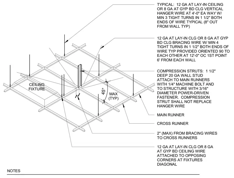
Suspended ceiling grid attachment and seismic bracing requirements for lay-in acoustic ceilings and gypsum board ceilings. Vertical hanger wires of twelve gauge for lay-in ceilings or eight gauge for gypsum board ceilings are spaced at four feet on center each way, featuring a minimum of three tight turns in one and a half inches at both ends and positioned eight inches out from the wall typical. Bracing wires of twelve gauge for lay-in ceilings or eight gauge for gypsum board ceilings are provided at twelve feet on center with the first point six feet from each wall, oriented ninety degrees to each other and secured with a minimum of four tight turns in one and a half inches. A compression strut consisting of a one and a half inch deep twenty gauge wall stud attaches to the main runners with a quarter inch machine bolt and to the structure with a three sixteenth inch diameter power-driven fastener, with cross runners located within two inches of the bracing wires. Diagonal wires are attached to opposing corners at ceiling fixtures at a maximum angle of forty-five degrees.
TYPICAL: 12 GA AT LAY-IN CEILING OR 8 GA AT GYP BD CLG VERTICAL HANGER WIRE AT 4'-0" EA WAY W/ MIN 3 TIGHT TURNS IN 1 1/2" BOTH ENDS OF WIRE TYPICAL (8" OUT FROM WALL TYP) 12 GA AT LAY-IN CLG OR 8 GA AT GYP BD CLG BRACING WIRE W/ MIN 4 TIGHT TURNS IN 1 1/2" BOTH ENDS OF WIRE TYP PROVIDED ORIENTED 90 TO EACH OTHER AT 12'-0" OC 1ST POINT 6' FROM EACH WALL COMPRESSION STRUTS: 1 1/2" DEEP 20 GA WALL STUD ATTACH TO MAIN RUNNERS WITH 1/4" MACHINE BOLT AND TO STRUCTURE WITH 3/16" DIAMETER POWER-DRIVEN FASTENER. COMPRESSION STRUT SHALL NOT REPLACE HANGER WIRE MAIN RUNNER CROSS RUNNER 2" (MAX) FROM BRACING WIRES TO CROSS RUNNERS CEILING FIXTURE 45° MAX (TYP) 12 GA AT LAY-IN CLG OR 8 GA AT GYP BD CEILING WIRE ATTACHED TO OPPOSING CORNERS AT FIXTURES DIAGONAL NOTES
Members view this detail in full resolution, download the CAD files (SVG, PDF), and can adapt it in the built-in CAD editor — export DXF, DWG, or PDF.
Start membership