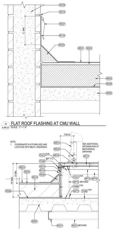
A flat roof assembly transitions up a concrete masonry unit wall with base flashing tied into the membrane system and counterflashing secured above. Insulation and roof decking bear on structural framing below, with a minimum seven-inch clearance maintained between the roof surface and flashing termination. Mechanical equipment supports tie into the structural assembly with coordinated platform attachments.
7" MIN. RD63 RD23 RD21 RD22 RD40 RD58 RD125 RD47 DD16 WD39 SEE ADDITIONAL INFORMATION AT MECHANICAL DRAWING NOTE: 1. COORDINATE PLATFORM SIZE AND LOCATION WITH MECH. DRAWINGS. RD19 RD22 RD40 FA46 @6" O.C. RD127 8" MIN. RD63 RD31 RD31 BEYOND 18" MAX. TYP. FA96 MF75 MF74 MF73 TYP. FA96 WD13 MF73 BEYOND RD125 RD58 ME03 ME01 ME02 7/S0.25 RD21 TYP. FA21 TYP. FA21 SCALE: 3" = 1'-0" A.M9.21 34 FLAT ROOF FLASHING AT CMU WALL
Members view this detail in full resolution, download the CAD files (SVG, PDF), and can adapt it in the built-in CAD editor — export DXF, DWG, or PDF.
Start membership