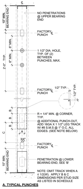
Cold-formed metal stud webs feature factory punches and field-drilled holes with specific clearance and spacing requirements. The upper and lower bearing ends require a minimum ten-inch clearance with no penetrations allowed at the upper bearing end. Additional punch-outs require a sixteen-gauge by one-and-a-half-inch leg track secured with number eight sheet metal screws at one inch on center along all edges. Two one-and-a-half-inch diameter service holes are typical between factory punches. Dimensions for cutouts and spacings are applied per the stud size listed in the schedule.
FACTORY PUNCH 6" MIN. 6" MIN. FACTORY PUNCH FACTORY PUNCH BEARING END 10" MIN. 2'-0" TYP. A B B B C NOTE: OMIT TRACK WHEN A ≤ 1/2(W). APPLY B & C DIMENSIONS PER STUD SIZE AS LISTED IN SCHEDULE 1/2" TYP. 1/2" TYP. 3/4" 1 1/2" DIA. HOLE, TYP. OF (2) BETWEEN PUNCHES, MAX. NO PENETRATIONS @ UPPER BEARING END R = 1/4" MIN. @ CORNER, TYP. @ ADDITIONAL PUNCH-OUT, ADD 16GA X 1 1/2" LEG TRACK W/ #8 S.M.S @ 1" O.C. ALL EDGES. (SEE NOTE BELOW) PENETRATION @ LOWER BEARING END, SEE 'B' A. TYPICAL PUNCHES BEARING END 10" MIN. 10" MIN.
Members view this detail in full resolution, download the CAD files (SVG, PDF), and can adapt it in the built-in CAD editor — export DXF, DWG, or PDF.
Start membership