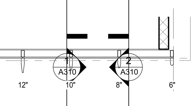
The drawing shows a horizontal assembly intersected by vertical reference lines with corresponding section markers for sheets 1 and 2 on A310. Dimension indicators mark intervals of twelve, ten, eight, and six inches along the reference axis. An insulated wall element connects at the upper right edge of the assembly. Dashed horizontal alignment lines run parallel through the reference points.
Members view this detail in full resolution, download the CAD files (SVG, PDF), and can adapt it in the built-in CAD editor — export DXF, DWG, or PDF.
Start membership