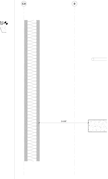
This plan detail shows a framed wall assembly positioned two feet four and five-eighths inches from a concrete structural element at Level 2. Grid lines C.9 and D establish the coordinate locations for the components. The wall features multiple layers including insulation and sheathing spanning between the grid lines.
Members view this detail in full resolution, download the CAD files (SVG, PDF), and can adapt it in the built-in CAD editor — export DXF, DWG, or PDF.
Start membership