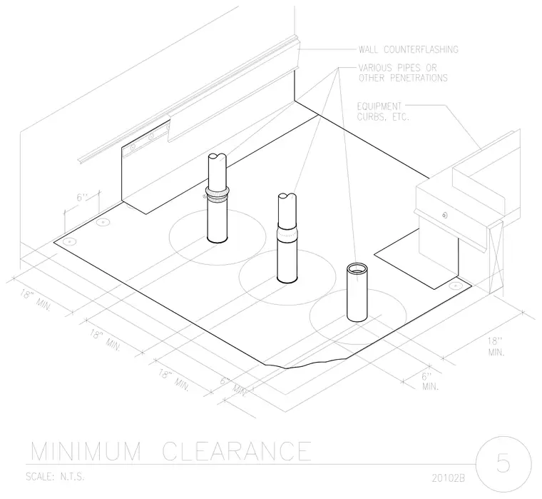
This isometric drawing details the minimum spacing requirements and clearances for roof penetrations, including various pipes and equipment curbs. The layout establishes an 18-inch minimum clearance between penetrations and walls, alongside a 6-inch minimum edge distance and spacing. Wall counterflashing is indicated along the vertical wall junction above the roof membrane. Additional notes highlight various pipes, other penetrations, and equipment curbs.
Members view this detail in full resolution, download the CAD files (SVG, PDF), and can adapt it in the built-in CAD editor — export DXF, DWG, or PDF.
Start membership