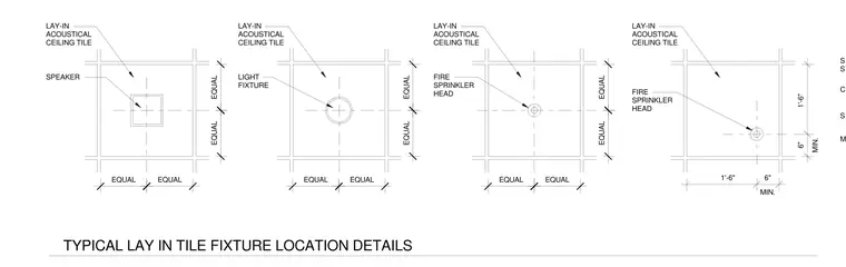
These details outline the positioning of ceiling-integrated equipment within lay-in acoustical ceiling tiles supported by a main tee splice suspension system and seismic restraint system with compression posts. The layout diagrams establish centering and spacing parameters for speakers, light fixtures, and fire sprinkler heads relative to the grid tiles. Dimensioning establishes equal spacing across tile modules, with specific edge clearances including a six inch minimum and one foot six inch spacing. Fixture placements are coordinated within the grid to maintain structural and seismic compliance for ceiling assemblies.
TYPICAL LAY IN TILE FIXTURE LOCATION DETAILS MAIN TEE SPLICE SUSPENSION SYSTEM SEISMIC RESTRAINT SYSTEM. COMPRESSION POST EQUAL EQUAL EQUAL EQUAL EQUAL EQUAL EQUAL EQUAL EQUAL EQUAL EQUAL EQUAL 6" MIN. 1'-6" 6" MIN. 1'-6" LAY-IN ACOUSTICAL CEILING TILE FIRE SPRINKLER HEAD LAY-IN ACOUSTICAL CEILING TILE FIRE SPRINKLER HEAD LAY-IN ACOUSTICAL CEILING TILE LIGHT FIXTURE LAY-IN ACOUSTICAL CEILING TILE SPEAKER
Members view this detail in full resolution, download the CAD files (SVG, PDF), and can adapt it in the built-in CAD editor — export DXF, DWG, or PDF.
Start membership