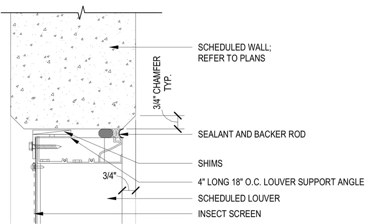
The louver head is secured to the underside of a scheduled concrete wall, which features a three-quarter-inch chamfer at the exterior corner. The louver frame is mounted using four-inch long support angles spaced at eighteen inches on center. Shims are installed between the support angle and the concrete substrate to ensure proper alignment. The perimeter joint between the louver frame and the concrete is finished with a backer rod and sealant. An insect screen is attached to the interior face of the louver assembly.
SCHEDULED WALL; REFER TO PLANS SCHEDULED LOUVER SHIMS 4" LONG 18" O.C. LOUVER SUPPORT ANGLE 02 A-60009 TYP INSECT SCREEN SEALANT AND BACKER ROD TYP. 3/4" CHAMFER 3/4"
Members view this detail in full resolution, download the CAD files (SVG, PDF), and can adapt it in the built-in CAD editor — export DXF, DWG, or PDF.
Start membership