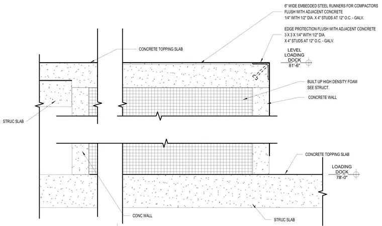
A loading bay platform section features structural concrete slabs with concrete topping slabs and concrete walls. The outer corner of the loading dock is detailed with a 3 by 3 by 1/4 inch galvanized steel edge protection angle featuring 1/2 inch diameter by 4 inch studs spaced at 12 inches on center, set flush with the adjacent concrete. The assembly includes 6 inch wide embedded galvanized steel runners for compactors, also installed flush with the adjacent concrete with 1/4 inch thickness and 1/2 inch diameter by 4 inch studs at 12 inches on center. Built-up high-density foam insulation is incorporated into the wall assembly as specified per structural drawings. Elevation levels are marked for the loading dock at 81'-6" and 78'-0".
S T R U C S L A B B U I L T U P H I G H D E N S I T Y F O A M S E E S T R U C T . C O N C R E T E T O P P I N G S L A B LOADING DOCK 78'-0" LEVEL LOADING DOCK 81'-6" C O N C R E T E T O P P I N G S L A B S T R U C S L A B C O N C R E T E W A L L C O N C W A L L E D G E P R O T E C T I O N F L U S H W I T H A D J A C E N T C O N C R E T E 3 X 3 X 1 / 4 " W I T H 1 / 2 " D I A . X 4 " S T U D S A T 1 2 " O . C . - G A L V . 6 " W I D E E M B E D D E D S T E E L R U N N E R S F O R C O M P A C T O R S F L U S H W I T H A D J A C E N T C O N C R E T E 1 / 4 " W I T H 1 / 2 " D I A . X 4 " S T U D S A T 1 2 " O . C . - G A L V .
Members view this detail in full resolution, download the CAD files (SVG, PDF), and can adapt it in the built-in CAD editor — export DXF, DWG, or PDF.
Start membership