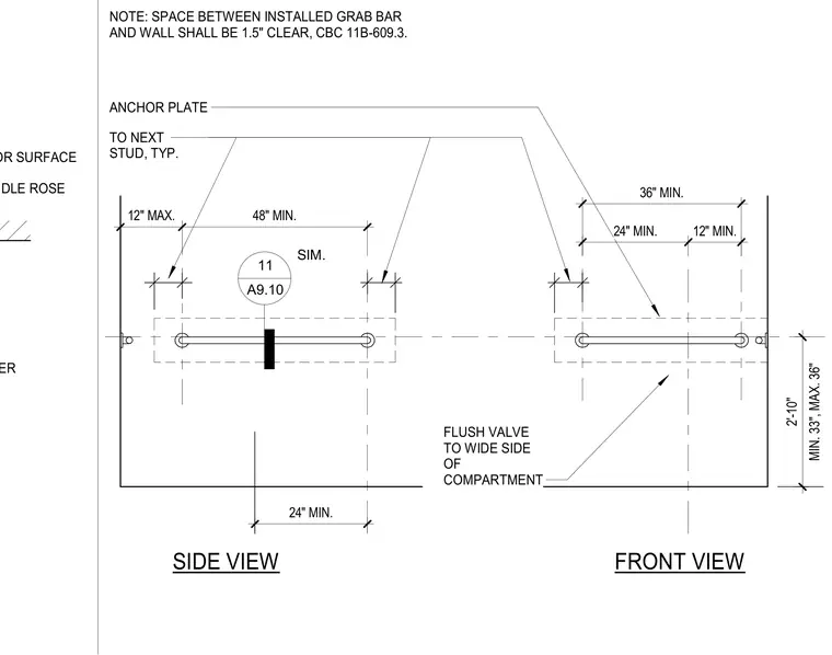
An ADA-compliant grab bar installation layout requires an anchor plate secured to the next stud with a minimum spacing of thirty-three to thirty-six inches from the finished floor to the top of the gripping surface. The clear space between the installed grab bar and the wall maintains a one-and-a-half-inch clearance in accordance with CBC 11B-609.3. The side and front views indicate a minimum twenty-four-inch horizontal bar length alongside a thirty-six-inch rear bar configuration, with the flush valve positioned on the wide side of the compartment.
ANCHOR PLATE TO NEXT STUD, TYP. MIN. 33", MAX. 36" 2'-10" FRONT VIEW SIDE VIEW 24" MIN. NOTE: SPACE BETWEEN INSTALLED GRAB BAR AND WALL SHALL BE 1.5" CLEAR, CBC 11B-609.3. 12" MAX. 48" MIN. 24" MIN. 12" MIN. 36" MIN. FLUSH VALVE TO WIDE SIDE OF COMPARTMENT 11 A9.10 SIM. LEVER HANDLE ROSE DOOR SURFACE
Members view this detail in full resolution, download the CAD files (SVG, PDF), and can adapt it in the built-in CAD editor — export DXF, DWG, or PDF.
Start membership