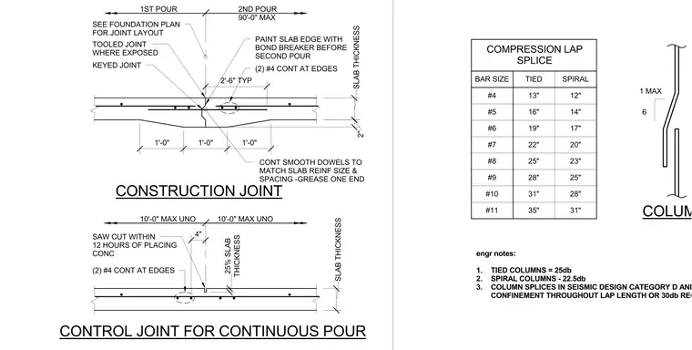
The construction joint detail features a keyed slab edge between the first and second pours, painted with a bond breaker and reinforced with two continuous number four rebars at the edges alongside continuous smooth dowels matching the slab reinforcement size and spacing with one end greased. The control joint for continuous pour utilizes a four-inch saw cut within twelve hours of placing concrete at twenty-five percent of the slab thickness, with two continuous number four rebars at the edges. A compression lap splice table specifies lap lengths for tied and spiral columns ranging from number four through number eleven bars, accompanied by engineering notes detailing seismic and confinement requirements for column splices.
1ST POUR 2ND POUR 90'-0" MAX SEE FOUNDATION PLAN FOR JOINT LAYOUT TOOLED JOINT WHERE EXPOSED PAINT SLAB EDGE WITH BOND BREAKER BEFORE SECOND POUR (2) #4 CONT AT EDGES SLAB THICKNESS 2" KEYED JOINT 1'-0" 1'-0" 1'-0" CONSTRUCTION JOINT 10'-0" MAX UNO 10'-0" MAX UNO 4" SAW CUT WITHIN 12 HOURS OF PLACING CONC (2) #4 CONT AT EDGES THICKNESS 25% SLAB SLAB THICKNESS CONTROL JOINT FOR CONTINUOUS POUR 2'-6" TYP CONT SMOOTH DOWELS TO MATCH SLAB REINF SIZE & SPACING -GREASE ONE END COMPRESSION LAP SPLICE BAR SIZE TIED SPIRAL #4 13" 12" #5 16" 14" #6 19" 17" #7 22" 20" #8 25" 23" #9 28" 25" #10 31" 28" #11 35" 31" engr notes: 1. TIED COLUMNS = 25db 2. SPIRAL COLUMNS - 22.5db 3. COLUMN SPLICES IN SEISMIC DESIGN CATEGORY D AND CONFINEMENT THROUGHOUT LAP LENGTH OR 30db REQUIRED. COLUMN 6 1 MAX
Members view this detail in full resolution, download the CAD files (SVG, PDF), and can adapt it in the built-in CAD editor — export DXF, DWG, or PDF.
Start membership