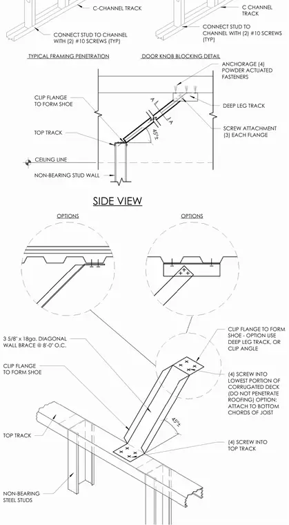
A non-bearing steel stud wall utilizes a three and five-eighths inch by eighteen gauge diagonal wall brace spaced at eight feet on center, anchored back to the overhead structure. The brace is formed with clip flanges acting as shoes at both ends and secured with three screws on each flange. At the top track intersection, the assembly connects with four screws into the top track, or alternatively utilizes a deep leg track or clip angle. The overhead attachment to the corrugated deck involves four screws into the lowest portion of the deck, ensuring fasteners do not penetrate the roofing, with an alternate option to attach directly to the bottom chords of the joist. Additionally, typical framing penetrations and door knob blocking details illustrate C-channel track connections using two number ten screws typical at stud-to-channel junctions.
DOOR KNOB BLOCKING DETAIL TYPICAL FRAMING PENETRATION CONNECT STUD TO CHANNEL WITH (2) #10 SCREWS (TYP) C CHANNEL TRACK C-CHANNEL TRACK CONNECT STUD TO CHANNEL WITH (2) #10 SCREWS (TYP) 45°± 45°± SCREW ATTACHMENT (3) EACH FLANGE CLIP FLANGE TO FORM SHOE A TOP TRACK CEILING LINE A SIDE VIEW NON-BEARING STUD WALL ANCHORAGE (4) POWDER ACTUATED FASTENERS CLIP FLANGE TO FORM SHOE - OPTION USE DEEP LEG TRACK, OR CLIP ANGLE (4) SCREW INTO LOWEST PORTION OF CORRUGATED DECK (DO NOT PENETRATE ROOFING) OPTION: ATTACH TO BOTTOM CHORDS OF JOIST (4) SCREW INTO TOP TRACK NON-BEARING STEEL STUDS CLIP FLANGE TO FORM SHOE 3 5/8" x 18ga. DIAGONAL WALL BRACE @ 8'-0" O.C. TOP TRACK OPTIONS OPTIONS DEEP LEG TRACK
Members view this detail in full resolution, download the CAD files (SVG, PDF), and can adapt it in the built-in CAD editor — export DXF, DWG, or PDF.
Start membership