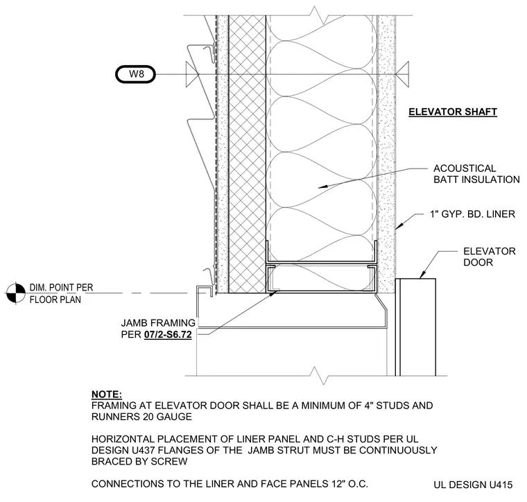
An exterior elevator door jamb assembly is framed with a minimum of four-inch studs and twenty-gauge runners. The shaft wall incorporates acoustical batt insulation and a one-inch gypsum board liner, with horizontal placement of liner panels and C-H studs complying with UL Design U437. Flanges of the jamb strut are continuously braced using screw connections to the liner and face panels at twelve inches on center. Framing at the elevator door is supported by structural steel framing members with dimension points located per the floor plan.
UL DESIGN U415 NOTE: FRAMING AT ELEVATOR DOOR SHALL BE A MINIMUM OF 4" STUDS AND RUNNERS 20 GAUGE HORIZONTAL PLACEMENT OF LINER PANEL AND C-H STUDS PER UL DESIGN U437 FLANGES OF THE JAMB STRUT MUST BE CONTINUOUSLY BRACED BY SCREW CONNECTIONS TO THE LINER AND FACE PANELS 12" O.C. FLOOR PLAN DIM. POINT PER ELEVATOR SHAFT ELEVATOR DOOR 1" GYP. BD. LINER ACOUSTICAL BATT INSULATION JAMB FRAMING PER 07/2-S6.72 W8
Members view this detail in full resolution, download the CAD files (SVG, PDF), and can adapt it in the built-in CAD editor — export DXF, DWG, or PDF.
Start membership