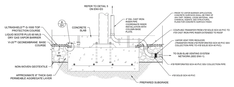
This sub-slab venting section details the integration of a gas vapor mitigation system beneath an eight-inch minimum concrete slab. A prepared subgrade supports an approximate eight-inch thick gas permeable aggregate layer wrapped in a non-woven geotextile. The assembly incorporates a sixty mil dry gas vapor barrier membrane with a geomembrane base course and a top protection course. A four-inch diameter perforated schedule forty polyvinyl chloride collection pipe collects soil gases within the aggregate layer and transitions via a reducer and coupling to a four-inch solid schedule forty polyvinyl chloride pipe. The venting network then connects to a four-inch diameter cast iron riser pipe extended to the roof, requiring careful coordination with the structural column base plate.
LIQUID BOOT ® PLUS 60 MILS DRY GAS VAPOR BARRIER VI-20 ™ GEOMEMBRANE BASE COURSE ULTRASHIELD ™ G-1000 TOP PROTECTION COURSE PREPARED SUBGRADE CONCRETE SLAB 8" MIN. APPROXIMATE 8" THICK GAS PERMEABLE AGGREGATE LAYER NON-WOVEN GEOTEXTILE 8 D1 MIN. 4.5" PRIOR TO VAPOR BARRIER APPLICATION, CONCRETE SURFACES SHALL BE FREE OF ANY DIRT, DEBRIS, LOOSE MATERIAL, AND CHEMICAL AGENTS. SEE STRUCTURAL PLANS FOR CONCRETE SURFACE FINISH. REFER TO DETAIL 5 ON ENV-D3 TO SUB-SLAB VENTING SYSTEM NETWORK (SEE ENV-1) 4"Ø PERFORATED SCH 40 PVC SSV COLLECTION PIPE 4"Ø SOLID SCH 40 PVC VAPOR VENT PIPE REDUCER (TRANSFER FROM 4"Ø PERFORATED SCH 40 PVC SSV COLLECTION PIPE TO 4"Ø SOLID SCH 40 PVC) COUPLING TRANSFER FROM 4"Ø SOLID SCH 40 PVC TO 4"Ø CAST IRON PIPE RISER EXTENDED TO ROOF 4" DIA. CAST IRON RISER PIPE. COORDINATE RISER INSTALLATION WITH COLUMN BASE PLATE.
Members view this detail in full resolution, download the CAD files (SVG, PDF), and can adapt it in the built-in CAD editor — export DXF, DWG, or PDF.
Start membership