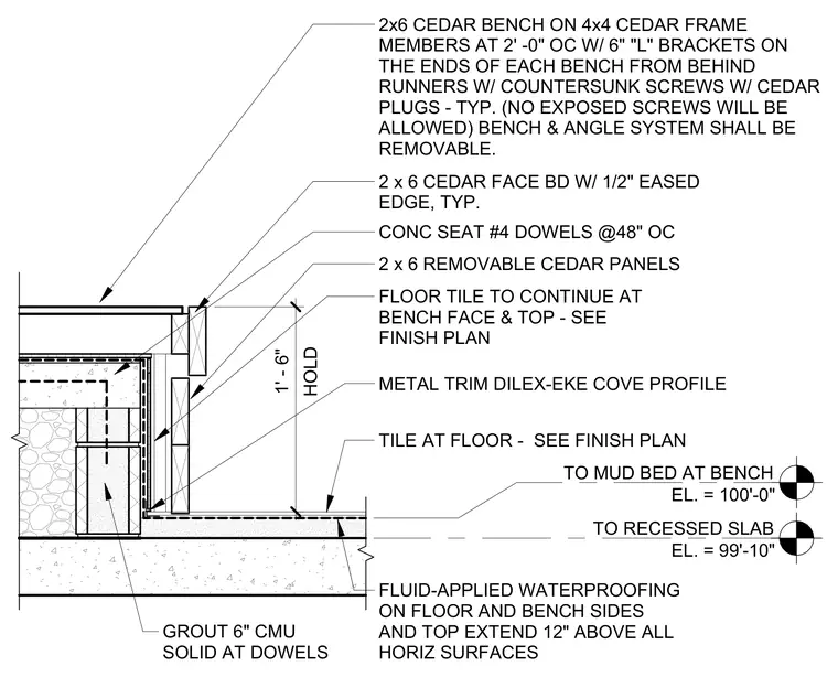
A sauna single bench assembly is anchored to a concrete seat and a six-inch concrete masonry unit wall. The concrete seat is reinforced with number four dowels spaced at forty-eight inches on center, supported by the six-inch concrete masonry unit wall with solid grout at dowels. Fluid-applied waterproofing is applied across the floor and bench sides and top, extending twelve inches above all horizontal surfaces. Floor tile continues across the bench face and top per the finish plan, meeting at a metal trim Dilex-Eke cove profile. The bench features two-by-six cedar face boards with a half-inch eased edge and two-by-six removable cedar panels supported by a four-by-four cedar frame at two feet on center. Six-inch L-brackets on the ends of each bench from behind runners use countersunk screws with cedar plugs to ensure no exposed screws are visible, and the entire bench and angle system remains removable.
TO MUD BED AT BENCH EL. = 100'-0" TO RECESSED SLAB EL. = 99'-10" 2 x 6 CEDAR FACE BD W/ 1/2" EASED EDGE, TYP. 2x6 CEDAR BENCH ON 4x4 CEDAR FRAME MEMBERS AT 2' -0" OC W/ 6" "L" BRACKETS ON THE ENDS OF EACH BENCH FROM BEHIND RUNNERS W/ COUNTERSUNK SCREWS W/ CEDAR PLUGS - TYP. (NO EXPOSED SCREWS WILL BE ALLOWED) BENCH & ANGLE SYSTEM SHALL BE REMOVABLE. FLOOR TILE TO CONTINUE AT BENCH FACE & TOP - SEE FINISH PLAN 2 x 6 REMOVABLE CEDAR PANELS FLUID-APPLIED WATERPROOFING ON FLOOR AND BENCH SIDES AND TOP EXTEND 12" ABOVE ALL HORIZ SURFACES TILE AT FLOOR - SEE FINISH PLAN GROUT 6" CMU SOLID AT DOWELS CONC SEAT #4 DOWELS @48" OC HOLD 1' - 6" METAL TRIM DILEX-EKE COVE PROFILE
Members view this detail in full resolution, download the CAD files (SVG, PDF), and can adapt it in the built-in CAD editor — export DXF, DWG, or PDF.
Start membership